|
|
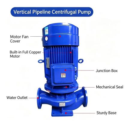
ISG Vertical Pipeline Centrifugal Pump mechanical room layout suggestionA well-planned mechanical room layout for ISG vertical pipeline centrifugal pumps directly cuts long-term maintenance risks, simplifies routine inspection, and prevents avoidable operational failures caused by cramped or poorly positioned equipment. Many teams rush equipment placement to meet tight construction timelines, only to discover later that critical access points are blocked, piping runs create unnecessary stress, and heat buildup degrades motor performance over time. Proper layout follows practical field experience rather than generic space allocation rules, and it balances installation efficiency, daily operability, and long-term service access for every connected system.
Clearance and Access Zone Planning Around Pump UnitsEvery pump unit requires dedicated free space around its full perimeter, not just the narrow footprint of the base itself. Leave at least 700mm of open clearance on the side facing the main service aisle, so technicians can stand comfortably to check oil levels, read pressure gauge readings, and operate nearby valves without squeezing into tight gaps. The area directly above the motor must remain completely unobstructed, with no pipes, cable trays, or structural beams blocking the vertical path needed to lift the motor and rotor assembly during major service. This overhead clearance eliminates the need to dismantle unrelated piping or structural components when performing seal replacement or impeller inspection. Reserve a separate small work zone near each pump bank, enough to lay down removed rotor parts and basic hand tools during maintenance, so components do not sit on damp floors or get knocked around by passing personnel. Avoid placing electrical control boxes directly above pump flanges, so accidental seal leakage will never drip onto live wiring and create electrical hazard. Keep all wall-mounted electrical panels positioned at least one meter away from any possible liquid spill path, and make sure no part of the pump unit blocks the emergency stop button that serves the whole system. Piping and Auxiliary System Layout OptimizationRoute all suction and discharge piping along clearly defined runs that do not cross over the top of pump motors, to prevent condensed moisture or trapped air from dripping onto winding surfaces. Every pipeline connected to the pump must have its own independent support structure mounted to the floor or building structure, so no pipe weight transfers onto the pump casing or flanges. This layout rule eliminates hidden pipeline stress that would otherwise pull the pump out of vertical alignment and cause premature bearing wear. Position suction piping runs to keep straight length at least five times the nominal pipe diameter before the pump inlet flange, with no sudden elbows, tees, or partially closed valves in that section. This arrangement ensures even flow distribution into the impeller eye, reduces turbulence, and prevents uneven pressure distribution that would increase cavitation risk. Mount pressure gauges on short, easy-to-reach standpipes instead of tucking them deep behind pipework, so operators can take accurate readings during routine rounds without using step stools or special tools. Arrange all isolation valves within arm’s reach from the main service aisle, so operators can shut down individual units quickly during an emergency without navigating around other equipment. Ventilation, Drainage and Environmental Layout ControlMechanical room ventilation must be designed to pull in cool fresh air at floor level near the pump base, and exhaust hot air at high points near the ceiling above the motor bank. This natural airflow pattern carries away the heat generated by running motors, prevents ambient temperature from climbing far above the design limit, and keeps motor winding insulation working within its rated temperature range. Avoid placing pump units directly in the path of unconditioned outdoor air intake that carries high levels of dust, moisture, or corrosive fumes, as these contaminants will gradually damage motor surfaces and shorten seal service life. Lay a sloped concrete curb around each pump installation zone, leading all spilled liquid and drainage to a dedicated floor sump located in a low corner of the room. Never route drainage paths across walkways or near electrical equipment, and make sure no standing water can accumulate around the pump base or motor footing. Position the sump at a point that does not require any pump unit to sit below the room’s general floor level, so accidental flooding will never submerge motor terminals or electrical connection boxes. Add dedicated cable trays mounted on wall brackets, separate from piping runs, so power and signal wiring stay dry, organized, and easy to trace during troubleshooting work. |