ISG Vertical Pipeline Centrifugal Pump field assembly operation steps
Field assembly of a vertical pipeline centrifugal pump requires careful, step-by-step execution to avoid hidden mechanical issues that could cause performance loss or premature failure. Every action on site should follow standard industrial practice, with each component inspected and verified before moving to the next stage. This hands-on approach helps ensure that the final assembled unit can operate reliably under design conditions without unnecessary vibration, leakage, or alignment errors.
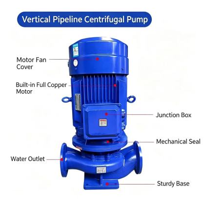
Pre-assembly site and component preparation
Before any assembly work begins, clear the designated installation area of all loose debris, leftover welding rods, and unused tools that could obstruct movement or fall into open pipe ends. Lay out all required components on a clean, flat surface close to the final mounting position, and check each part for visible damage that may have occurred during transportation. Rotate the pump shaft manually several full turns to confirm no internal rubbing, binding, or unexpected resistance exists. Verify that the foundation surface is level and all anchor bolt positions match the unit’s footprint, so no forced adjustment will be needed when lowering the pump into place. This preparation stage prevents most common assembly delays and reduces the risk of overlooking small but critical details.
Pump body and motor alignment assembly
Position the pump casing carefully over the pre-laid anchor bolts, and adjust its orientation until the suction and discharge flanges align naturally with the corresponding pipeline centerlines. Tighten the anchor bolts gradually in a diagonal sequence to distribute clamping force evenly, while continuously checking the unit’s verticality with a precision level placed on the motor mounting surface. For close-coupled configurations, carefully lower the motor onto the pump bracket, making sure the motor extension shaft slides smoothly into the impeller bore without applying lateral force. Rotate the combined shaft assembly by hand again to confirm the entire rotating group turns freely, with no sign of scraping or uneven resistance that could indicate misalignment between pump and motor components.
Flange connection and auxiliary component installation
Place a full, undamaged sealing gasket between each pump flange and the corresponding pipe flange, then insert all flange bolts before starting any tightening operation. Tighten each flange bolt in a slow, cross-pattern sequence, so the gasket compresses uniformly and no localized gap remains that could cause leakage under pressure. Install the suction-side filter upstream of the pump casing, making sure its mesh size is appropriate to block welding slag, rust particles, and other debris from entering the impeller chamber. Mount the pressure gauge ports, air vent valve, and any required flexible connectors according to the system layout, ensuring each auxiliary part is secured firmly and oriented for easy observation and future maintenance. Once all connections are complete, perform another manual shaft rotation check to confirm no pipe stress has shifted the internal alignment during flange fastening.
Recommend
-

-

QQ Zone
-

Sina Weibo
-

Renren.com
-

Douban